Quick Start Guide#
This section provides instructions on how to hook up your board. This Beagle requires a 5V @ 1A (5W) power supply to work properly via either USB Type-C power adapter or via cape header pins.
Recommended adapters can be found at Power supplies section.
What’s In the Box#
In the box you will find two main items,
Instruction card
Note
A USB-C to USB-C / USB-A to USB-C cable is not included, but recommended for the tethered scenario and creates a developer experience where the board can be used immediately with no other equipment needed.
Tip
For board files, 3D model, and more, you can checkout PocketBeagle 2 repository on OpenBeagle.
Software Updates#
Follow instructions below to download the latest image for your PocketBeagle 2:
Go to Beagleboard Imager page.
Select board, image, drive and hit
WRITE.Pop the sdcard into the card-slot on the back, with the pretty side facing out.
Power on your Beagle and let it rip!
Important
Tip
copy microSD to eMMC optionTo see what SW revision is loaded into the running software image, check /etc/dogtag. It should look something like as shown in example below:
root@BeagleBone:~# cat /etc/dogtag
BeagleBoard.org Debian Trixie IOT Image 2026-02-12
Main Connection Scenarios#
This section describes how to connect and power the board and serves as a slightly more detailed description of the quick start guide included in the box. The board can be configured in several different ways, but we will discuss the two most common scenarios.
Directly tethered to a PC via pocketbeagle 2 USB-C port.
With TechLab Cape or GamePup Cape for sensors, USB host, LEDs and Buttons.
Tethered Connection#
In this scenario, the board is directly connected to a PC via USB-C port. This is the simplest way to get started with the board. Optionally you can connect rpi debug probe to 3-pin JST-SH connector to see boot log, board console access and for general debugging.
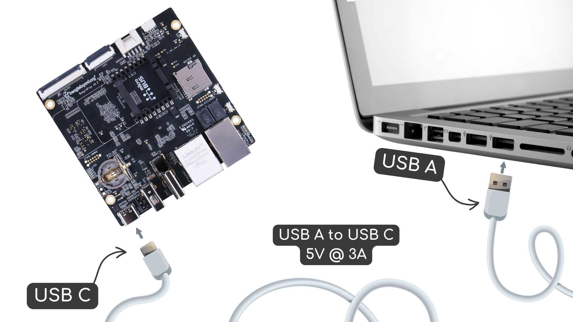
Fig. 213 Tethered Connection#
USB connection#
Connect the USB-C cable to the PocketBeagle 2 and the other end to the PC.
The board will power up and boot from the microSD card.
The board will show up as a USB device on the PC.
You can access the board via
SSHor boardserialconnection or thoughVisual Studio Code Serverweb interface.
After connecting the board to the PC, you can access the board via a web browser by entering the IP address of the board in the address bar.
https://192.168.7.2:3000/
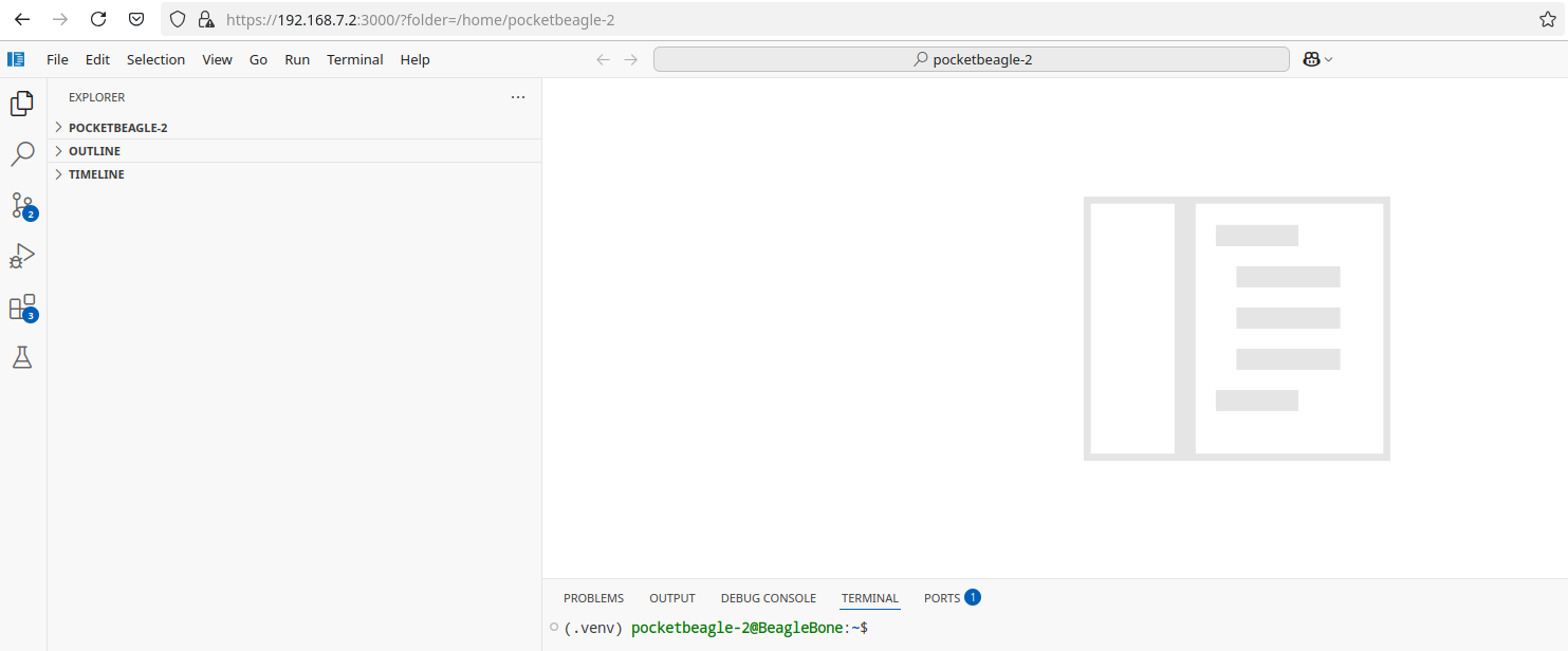
Fig. 214 Visual Studio Code Server#
After connecting the board to the PC, you can access the board via SSH executing the following command in your terminal.
ssh <username>@192.168.7.2
Where <username> is the username you selected during the microSD card flashing process.
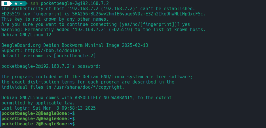
Fig. 215 SSH connection#
PocketBeagle 2 has a built-in UART debug connection. You can connect to the board console using a serial console application (e.g. Putty) on the PC just like your would connection using any external UART debug probe
If PocketBeagle 2 is the old device connected with UART, on linux you can use tio utility, replace ttyACMx with the actual device name.
tio /dev/ttyACMx
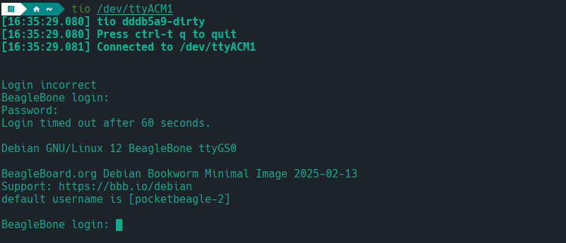
Fig. 216 Serial connection#
Once you have access to the console using any of the methods above, you might want to share internet connection with the board. Do this by following the OS specific steps below:
First you have to identify your WiFi interface name and PocketBeagle 2 Ethernet interface name using following command,
ip a
If you have your WiFi connected to router and PB2 connected to one of the USB the you should see four interfaces listed
1: lo
2: wlp0s20f3
3: enp0s20f0u2
4: enp0s20f0u2i2
Out of which wlp0s20f3 is the WiFi interface and enp0s20f0u2 is the PocketBeagle 2 Ethernet interface.
Once you know the interface names, you have to create pc-internet.sh file on PC with the following content,
sudo sysctl net.ipv4.ip_forward=1
sudo iptables --table nat --append POSTROUTING --out-interface wlp0s20f3 -j MASQUERADE
sudo iptables --append FORWARD --in-interface enp0s20f0u1 -j ACCEPT
make sure to update line 2 and 3 with your WiFi and PocketBeagle 2 Ethernet interface names. Then execute following commands,
chmod +x pc-internet.sh
sudo ./pc-internet.sh
Important
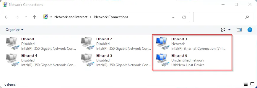
Ethernet 3, choose Properties and select the Share tab.Ethernet 6 from the dropdown.Ethernet 3 has changed to shared,sudo ip addr flush dev usb0
sudo dhclient usb0
After this, you can confirm that you can see the “outside world” by performing a ping.
Note
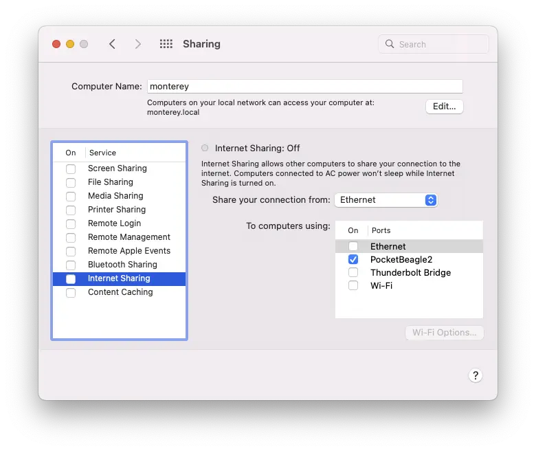
PocketBeagle2 in the To pane,sudo ip addr flush dev usb0
sudo dhclient usb0
After this, you can confirm that you can see the “outside world” by performing a ping.
UART serial debug connection#
Connect the rpi debug probe to the 3-pin JST-SH connector on the board.
Connect the other end of the probe to the PC.
Use command line utility like tio with default setting or a serial console application (e.g. Putty) to accress your board.
You will see the boot log and can access the board console.
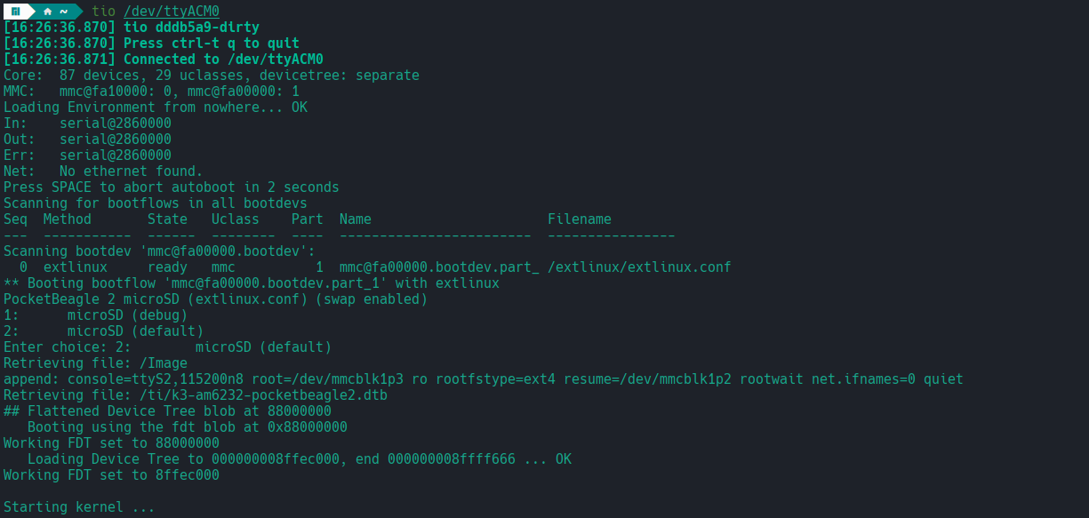
Fig. 217 Serial debug#
Cape Connection#
In this scenario, the board is connected to a cape like TechLab Cape or GamePup Cape. This is the most common way to use the board for sensor interfacing, USB host, LEDs and Buttons.