Design and specifications#
If you want to know how BeaglePlay is designed and the detailed specifications, then this chapter is for you. We are going to attempt to provide you a short and crisp overview followed by discussing each hardware design element in detail.
Tip
You can download BeaglePlay schematic to have clear view of all the elements that makes up the BeaglePlay hardware.
Block diagram#
The block diagram below shows all the parts that makes up your BeaglePlay board. BeaglePlay as mentioned in previous chapters is based on AM6254 SoC which is shown in the middle. Connection of other parts like power supply, memory, storage, wifi, ethernet, and others is also clearly shown in the block diagram. This block diagram shows the high level specifications of the BeaglePlay hardware and the sections below this are going to show you the individual part in more detail with schematic diagrams.

System on Chip (SoC)#
AM62x Sitara™ Processors from Texas Instruments are Human-machine-interaction SoC with Arm® Cortex®-A53-based edge AI and full-HD dual display. AM6254 which is on your BeaglePlay board has a multi core design with Quad 64-bit Arm® Cortex®-A53 microprocessor subsystem at up to 1.4 GHz, Single-core Arm® Cortex®-M4F MCU at up to 400MHz, and Dedicated Device/Power Manager. Talking about the multimedia capabilities of the processor you can connect upto two display monitors with 1920x1080 @ 60fps each, additionally there is a OLDI/LVDS (4 lanes - 2x) and 24-bit RGB parallel interface for connecting external display panels. One 4 Lane CSI camera interface is also available which has support for 1,2,3 or 4 data lane mode up to 2.5Gbps speed. The list of features is very long and if you are interested to know more about the AM62x SoC you may take a look at AM62x Sitara™ Processors datasheet.

Fig. 161 AM6254 SoC block diagram#
Power management#
Different parts of the board requires different voltages to operate and to fulfill requirements of all the chips on BeaglePlay we have Low Drop Out (LDO) voltage regulators for fixed voltage output and Power Management Integrated Circuit (PMIC) that interface with SoC to generate software programable voltages. 2 x LDOs and 1 x PMIC used on BeaglePlay are shown below.

1.0V LDO#
TLV75801 is an adjustable 500-mA low-dropout (LDO) regulator. Consumes very low quiescent current and provides fast line and load transient performance. The TLV758P features an ultra-low dropout of 130 mV at 500 mA that can help improve the power efficiency of the system. The TLV758P is stable with small ceramic output capacitors, allowing for a small overall solution size. A precision band-gap and error amplifier provides high accuracy of 0.7% (max) at 25°C and 1% (max) over temperature (85°C). This device includes integrated thermal shutdown, current limit, and undervoltage lockout (UVLO) features. The TLV758P has an internal foldback current limit that helps reduce the thermal dissipation during short-circuit events.

Fig. 162 TLV75801PDBVR LDO schematic for 1V0 output#
TLV75801 provides 1.0V required by the single-pair Ethernet PHY (U13 - DP83TD510ERHBR). It was decided this was less likely to be needed than the other rails coming off of the primary PMIC and therefore was given its own regulator when running low on power rails.
Note
The voltage drop from 1.8V to 1.0V is rated up to 0.3A (240mW), but the typical current from the DP83TD51E data sheet (SNLS656C) is stated at 3.5mA (2.8mW) and the maximum is 7.5mA (6mW). This isn’t overly significant on a board typically consuming 400mA at 5V (2W). However, this is an area where some power optimization could be performed if concerned about sleep modes.
3.3V DCDC buck#
TLV62595 is a high-frequency synchronous step-down converter optimized for compact solution size and high efficiency. The device integrates switches capable of delivering an output current up to 4 A. At medium to heavy loads, the converter operates in pulse width modulation (PWM) mode with typical 2.2-MHz switching frequency. At light load, the device automatically enters Power Save Mode (PSM) to maintain high efficiency over the entire load current range with a quiescent current as low as 10 μA.

Fig. 163 TLV62595DMQ step-down regulator schematic for 3V3 output#
This provides 3.3V for the vast majority of 3.3V I/Os on the board, off-board 3.3V power to microSD, mikroBUS, QWIIC and Grove connectors, as well as to the PMIC LDO to provide power for the 1.8V on-board I/Os, DDR4, and gigabit Ethernet PHY. Due to the relatively high current rating (3A), a highly efficient (up to 97%) was chosen.
Note
The primary TPS65219 PMIC firmware uses GPO2 to provide the enable signal (VDD_3V3_EN). The power-good signal (VDD_3V3_PG) is available at TP19 and is unused on the rest of the board.
PMIC#
The TPS65219 is a Power Management IC (PMIC) designed to supply a wide range of SoCs in both portable and stationary applications. The DC-DC converters are capable of 1x 3.5 A and 2x 2 A. The converters require a small 470 nH inductor, 4.7 μF input capacitance, and a minimum 10 μF output capacitance per rail. Two of the LDOs support output currents of 400 mA at an output voltage range of 0.6 V to 3.4 V. These LDOs support bypass mode, acting as a load- switch, and allow voltage-changes during operation. The other two LDOs support output currents of 300 mA at an output voltage range of 1.2 V to 3.3 V. The LDOs also support load-switch mode. The I2C-interface, IOs, GPIOs and multi-function-pins (MFP) allow a seamless interface to a wide range of SoCs.

Fig. 164 TPS65219 Power Management Integrated Circuit (PMIC) schematic#
This is the primary power management integrated circuit (PMIC) for the design. It coordinates the power sequencing and provides numerous power rails required for the core of the system, including dynamic voltages for the processor core and microSD card. The TPS6521903 variant is used for this DDR4-based system. The 03 at the end indicates the sequencing programmed into the device and is covered in the TPS6521903 Technical Reference Manual SLVUCJ2.
General Connectivity and Expansion#
One of the main advantage of using a Single Board Computer (SBC) is having direct accessibility of
general purpose input & output (GPIO) pins and other interfaces like I2C, SPI, ADC, PWM. Your BeaglePlay
board shines in this domain as well with mikroBUS connector that can take 1000s of click board from
MikroElektronika, Grove connector allows to connect hundreds of Grove modules
from Seeed Studio, and QWIIC connector allows to connect I2C modules
like QWIIC modules from SparkFun or STEMMA QT modules from
Adafruit. Note that you also get one USB-A port and one USB-C port.
BeaglePlay’s USB-A port with host support enables you to connect any USB device like your keyboard & mouse.
The USB-C connector allows you to power the board and to connect the board to a PC. You can then connect via SSH or
use the pre-installed VisualStudio Code editor by putting the address 192.168.7.2:3000 in your web browser.
USB A & USB C#
Below is the schematic of full size USB A for peripheral connection and USB C for device power & tethering.

Fig. 165 USB-A and USB-C#
2ch 10bit ADC#
The ADC102S051 is a low-power, two-channel CMOS 10-bit analog-to-digital converter with a high- speed serial interface. Unlike the conventional practice of specifying performance at a single sample rate only, the ADC102S051 is fully specified over a sample rate range of 200 ksps to 500 ksps. The converter is based on a successive-approximation register architecture with an internal track-and-hold circuit. It can be configured to accept one or two input signals at inputs IN1 and IN2. The output serial data is straight binary, and is compatible with several standards, such as SPI, QSPI, MICROWIRE, and many common DSP serial interfaces. We ar using it over SPI. The ADC102S051 operates with a single supply that can range from +2.7V to +5.25V. Normal power consumption using a +3V or +5V supply is 2.7 mW and 8.6 mW, respectively. The power-down feature reduces the power consumption to just 0.12 μW using a +3V supply, or 0.47 μW using a +5V supply.

Fig. 166 ADC102S051 - 12bit Analog to Digital Converter (ADC)#
mikroBUS#
mikroBUS is a standard specification by MikroElektronika that can be freely used by anyone following the guidelines. It includes SPI, I2C, UART, PWM, ADC, reset, interrupt, and power (3.3V and 5V) connections to common embedded peripherals.

Fig. 167 mikroBUS connector schematic#
Grove#
Seeed Studio Grove System is a modular, standardized connector prototyping ecosystem. The Grove System takes a building block approach to assembling electronics. Compared to the jumper or solder based system, it is easier to connect devices to an application, simplifying the learning system

Fig. 168 Grove connector schematic#
QWIIC#
Qwiic, or STEMMA QT are 4pin JST SH 1.00 connectors for easy I2C connection.

Fig. 169 QWIIC connector for I2C modules#
Buttons and LEDs#
To interact with the Single Board Computers we use buttons for input and LEDs for visual feedback. On your BeaglePlay board you will find 3 buttons each with a specific purpose: power, reset, and user. For visual feedback you will find 5 user LEDs near USB-C port and 6 more indicator LEDs near your BeaglePlay’s Single Pair ethernet port. Schematic diagrams below show how these buttons and LEDs are wired.
Buttons#
Power, Reset and User buttons for turning board ON/OFF, resetting board, and boot selection or user assigned control.
Power |
Reset |
User |
|---|---|---|

|

|
|
LEDs#
Power and user LEDs for status and general purpose usage.

Fig. 170 BeaglePlay LEDs#
Wired and wireless connectivity#
For internet connection or general connectivity between BeaglePlay and other devices.
Gigabit ethernet#
The Realtek RTL8211F-CG is a highly integrated Ethernet transceiver that is compatible with 10Base-T, 100Base-TX, and 1000Base-T IEEE 802.3 standards. It provides all the necessary physical layer functions to transmit and receive Ethernet packets over CAT.5 UTP cable. The RTL8211F(I)-CG uses state-of-the-art DSP technology and an Analog Front End (AFE) to enable high-speed data transmission and reception over UTP cable. Functions such as Crossover Detection & Auto-Correction, polarity correction, adaptive equalization, cross-talk cancellation, echo cancellation, timing recovery, and error correction are implemented in the RTL8211F(I)-CG to provide robust transmission and reception capabilities at 10Mbps, 100Mbps, or 1000Mbps.

Fig. 171 Gigabit ethernet#
Single pair ethernet#
The DP83TD510E is an ultra-low power Ethernet physical layer transceiver compliant with the IEEE 802.3cg 10Base-T1L specification. The PHY has very low noise coupled receiver architecture enabling long cable reach and very low power dissipation. The DP83TD510E has external MDI termination to support intrinsic safety requirements. It interfaces with MAC layer through MII, Reduced MII (RMII) , RGMII, and RMII low power 5-MHz master mode. It also supports RMII back-to-back mode for applications that require cable reach extension beyond 2000 meters. It supports a 25MHz reference clock output to clock other modules on the system. The DP83TD510E offers integrated cable diagnostic tools; built-in self- test, and loopback capabilities for ease of design or debug

Fig. 172 Single pair ethernet#
WiFi 2.4G/5G#
The WL18x7MOD is a Wi-Fi, dual-band, 2.4- and 5-GHz module solution with two antennas supporting industrial temperature grade. The device is FCC, IC, ETSI/CE, and TELEC certified for AP (with DFS support) and client. TI offers drivers for high-level operating systems, such as Linux® and Android™. Additional drivers, such as WinCE and RTOS, which includes QNX, Nucleus, ThreadX, and FreeRTOS, are supported through third parties.

Fig. 173 WL1807MOD dual-band (2.4G/5G) WiFi#
BLE & SubGHz#
The SimpleLink™ CC1352P7 device is a multiprotocol and multi-band Sub-1 GHz and 2.4-GHz wireless microcontroller (MCU) supporting Thread, Zigbee®, Bluetooth® 5.2 Low Energy, IEEE 802.15.4g, IPv6-enabled smart objects (6LoWPAN), mioty®, Wi-SUN®, proprietary systems, including the TI 15.4-Stack (Sub-1 GHz and 2.4 GHz), and concurrent multiprotocol through a Dynamic Multiprotocol Manager (DMM) driver. The CC1352P7 is based on an Arm® Cortex® M4F main processor and optimized for low-power wireless communication and advanced sensing in grid infrastructure, building automation, retail automation, personal electronics and medical applications.
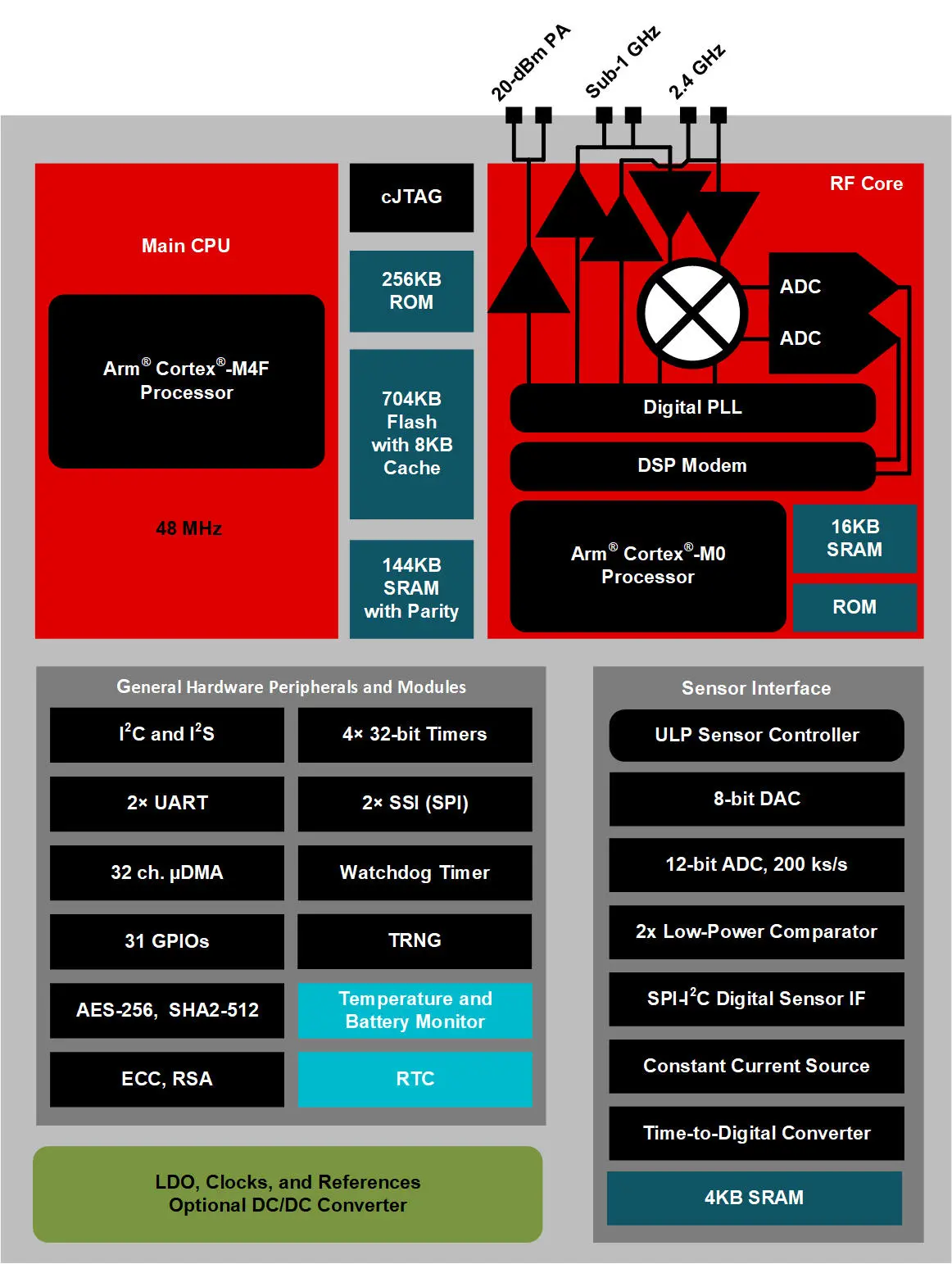
Fig. 174 CC1352P7 block diagram#

Fig. 175 CC1352P7 Bluetooth Low Energy (BLW) and SubGHz connectivity#
Memory, Media and Data storage#
DDR4#

Fig. 176 DDR4 Memory#
eMMC/SD#

Fig. 177 eMMC/SD storage#
microSD Card#

Fig. 178 microSD Card storage slot#
Board EEPROM#

Fig. 179 Board EEPROM ID#
Multimedia I/O#
HDMI#

Fig. 180 HDMI output#
OLDI#

Fig. 181 OLDI display interface#
CSI#

Fig. 182 CSI camera interface#
RTC & Debug#
RTC#

Fig. 183 Real Time Clock (RTC)#
UART Debug Port#

Fig. 184 UART debug port#
AM62x JTAG & TagConnect#

Fig. 185 AM62 JTAG debug port and TagConnect interface#
CC1352 JTAG & TagConnect#

Fig. 186 CC1352 JTAG debug port and TagConnect interface#
Mechanical Specifications#
Dimensions & Weight#
Parameter |
Value |
|---|---|
Size |
82.5x80x20mm |
Max heigh |
20mm |
PCB Size |
80x80mm |
PCB Layers |
8 layers |
PCB Thickness |
1.6mm |
RoHS compliant |
Yes |
Weight |
55.3g |
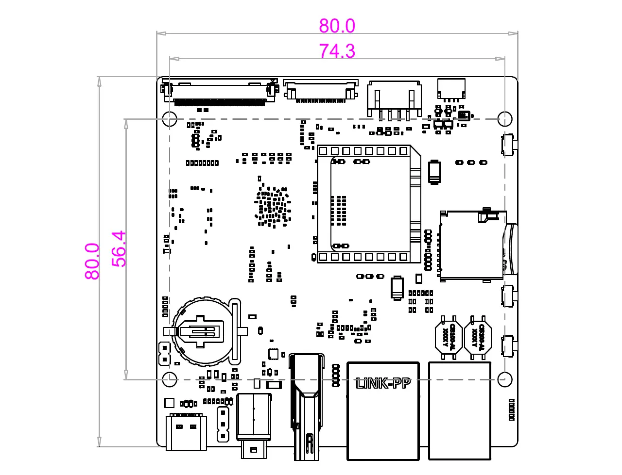
Fig. 187 BeaglePlay board dimensions#
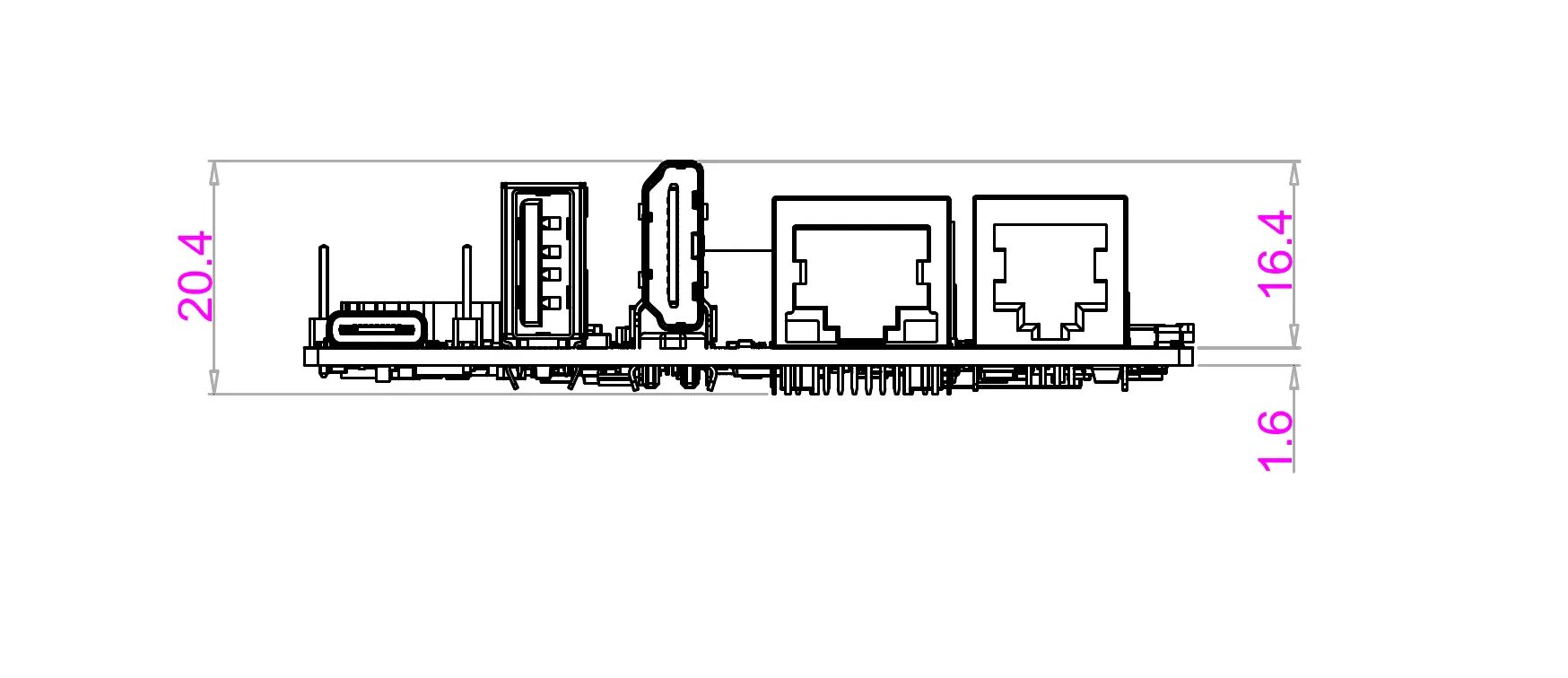
Fig. 188 BeaglePlay board side dimensions#
