Accessing APB and AXI Peripherals Through Linux#
AXI#
APB#
Accessing AXI and APB Peripherals from Linux#
/dev/mem interface and AXI peripherals using the UIO (Userspace I/O) framework.Note
The codes for accessing the interfaces are available in the snippets here: APB Interfaces and AXI Interfaces
APB Interfaces#
Design Details#
For this example, you can try to write to the APB slave present in the Verilog Tutorial Cape gateware.
Select the gateware by changing custom-fpga-design/my_custom_fpga_design.yaml to include VERILOG_TUTORIAL as the cape option.
The APB Slave has two registers, one read-only register at 0x00, one read-write register at 0x10, and a status register containing the last read value at 0x20.
0xXX10_0000 address, the top two bits being ignored.0xX100_0000 address.0x4000_0000 address.0x4110_0000.Now, we shall access this address through a memory-mapped interface in Linux.
Important
Accessing the Interface#
There are two ways to access such registers. One can use the devmem2 utility or write a C program for accessing the memory region. The first method is quite simple.
To read from a register:
sudo devmem2 0x41100000 w
To write to a register:
sudo devmem2 0x41100010 w 0x1
In the second method, we can use the /dev/mem interface to access the registers inside the APB Slave.
Here is an example C program which demonstrates this:
AXI Interfaces#
The MSS includes three 64-bit AXI FICs out of which FIC0 is used for data transfers to/from the fabric. FIC0 is connected as both master and slave. For usage of AXI peripherals, an example is also provided by microchip in their Polarfire SoC Linux examples. The example here takes reference from the AXI LSRAM example.
Design Details#
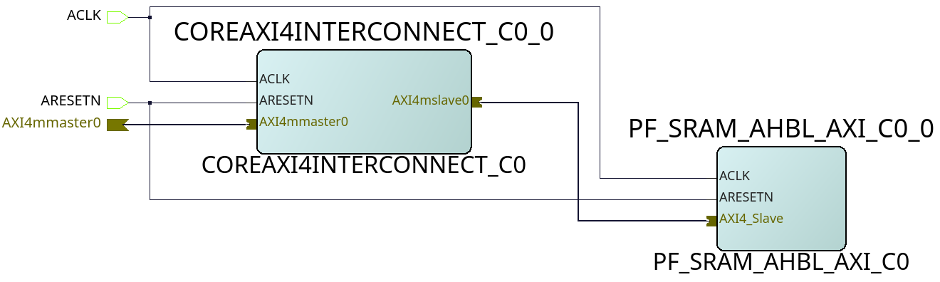
Fig. 608 AXI LSRAM slave (example design)#
Finally, an entry will be added to the device tree to make a UIO device point to our LSRAM’s memory region.
&{/} {
    fabric-bus@40000000 {
        fpgalsram: uio@60000000 {
            compatible = "generic-uio";
            linux,uio-name = "fpga_lsram"; // mandatory for program. If changed, please update program as well.
            reg = <0x0 0x60000000 0x0 0x1000>;
            status = "enabled";
        };
    };
};
Once the gateware is compiled, we can access the memory-mapped interface by the same methods, and by the UIO device as well.
Using devmem2:
sudo devmem2 0x60000000 w # for read
sudo devmem2 0x60000000 w 0x1 # for write
Using the UIO device:
Issues that can be faced when using an improperly configured AXI/APB interface#
A CPU stall can be faced when accessing the FIC interfaces without any slaves connected to the memory region being accessed. Your BVF will stop responding if connected to SSH, and on serial you will see the following kernel messages:
[   24.110099] rcu: INFO: rcu_sched detected stalls on CPUs/tasks:
[   24.116041] rcu:     0-...0: (1 GPs behind) idle=e00c/0/0x1 softirq=40/41 fqs=2626
[   24.123377]     (detected by 3, t=5255 jiffies, g=-1131, q=9 ncpus=4)
[   24.129573] Task dump for CPU 0:
[   24.132810] task:swapper/0       state:R  running task     stack:0     pid:0     ppid:0      flags:0x00000008
[   24.142757] Call Trace:
[   24.145213] [<ffffffff80a67ba0>] __schedule+0x27c/0x834
If this happens, please double check your design. Specifically, check the address configured for the slaves, the AXI ID wire width and other AXI parameters.
In any case, this state is virtually impossible to recover from gracefully, so the reset button may be your last resort.
