Debugging and Benchmarking#
One of the challenges is getting debug
information out of the PRUs since they don’t have a traditional printf().
In this chapter four different methods are presented that I’ve found useful in
debugging. The first is simply attaching an LED. The second is using
dmesg to watch the kernel messages. prudebug, a simple debugger that
allows you to inspect registers and memory of the PRUs, is then presented.
Finally, using one of the UARTS to send debugging information out a serial port
is shown.
Debugging via an LED#
Problem#
I need a simple way to see if my program is running without slowing the real-time execution.
Solution#
One of the simplest ways to do this is to attach an LED to the output pin and watch it flash. LED used for debugging P9_29 shows an LED attached to pin P9_29 of the BeagleBone Black.
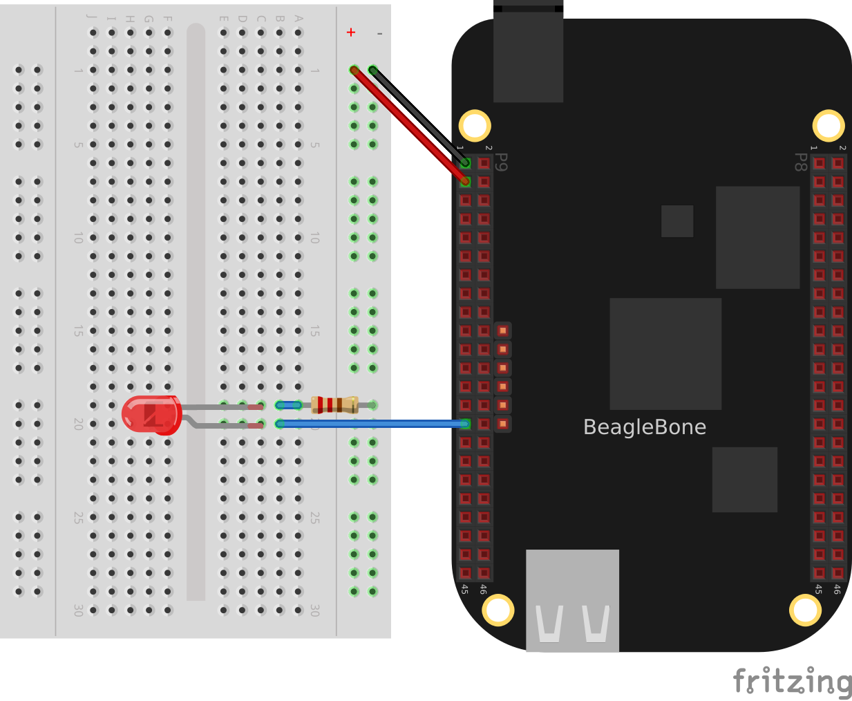
Fig. 788 LED used for debugging P9_29#
Make sure you have the LED in the correct way, or it won’t work.
Discussion#
If your output is changing more than a few times a second, the LED will be blinking too fast and you’ll need an oscilloscope or a logic analyzer to see what’s happening.
Another useful tool that let’s you see the contents of the registers and RAM is discussed in prudebug - A Simple Debugger for the PRU.
dmesg Hw#
Problem#
I’m getting an error message
(/sys/devices/platform/ocp/4a326000.pruss-soc-bus/4a300000.pruss/4a334000.pru0/remoteproc/remoteproc1/state: Invalid argument)
when I load my code, but don’t know what’s causing it.
Solution#
The command dmesg outputs useful information when dealing with the kernel.
Simply running dmesg -Hw can tell you a lot. The -H flag puts the
dates in the human readable form, the -w tells it to wait for more information.
Often I’ll have a window open running dmesg -Hw.
Here’s what dmesg said for the example above.
dmesg -Hw#
[  +0.000018] remoteproc remoteproc1: header-less resource table
[  +0.011879] remoteproc remoteproc1: Failed to find resource table
[  +0.008770] remoteproc remoteproc1: Boot failed: -22
It quickly told me I needed to add the line #include "resource_table_empty.h"
to my code.
prudebug - A Simple Debugger for the PRU#
Problem#
You need to examine registers and memory on the PRUs.
Solution#
prudebug is a simple debugger for the PRUs that lets you start and stop the PRUs and
examine the registers and memory. It can be found on GitHub
RRvW/prudebug-rl. I have a version I updated to use byte
addressing rather than word addressing. This makes it easier to work with the
assembler output. You can find it in my GitHub BeagleBoard repo
MarkAYoder/BeagleBoard-exercises.
Just download the files and type make.
Discussion#
Once prudebug is installed is rather easy to use.
Note
prudebug has now been ported to the AI.
bone$ *sudo prudebug*
PRU Debugger v0.25
(C) Copyright 2011, 2013 by Arctica Technologies.  All rights reserved.
Written by Steven Anderson

Using /dev/mem device.
Processor type                AM335x
PRUSS memory address  0x4a300000
PRUSS memory length   0x00080000

        offsets below are in 32-bit byte addresses (not ARM byte addresses)
        PRU            Instruction    Data         Ctrl
        0              0x00034000     0x00000000   0x00022000
        1              0x00038000     0x00002000   0x00024000
You get help by entering help. You cal also enter hb to get a brief help.
PRU0> *hb*
Command help

    BR [breakpoint_number [address]] - View or set an instruction breakpoint
    D memory_location_ba [length] - Raw dump of PRU data memory (32-bit byte offset from beginning of full PRU memory block - all PRUs)
    DD memory_location_ba [length] - Dump data memory (32-bit byte offset from beginning of PRU data memory)
    DI memory_location_ba [length] - Dump instruction memory (32-bit byte offset from beginning of PRU instruction memory)
    DIS memory_location_ba [length] - Disassemble instruction memory (32-bit byte offset from beginning of PRU instruction memory)
    G - Start processor execution of instructions (at current IP)
    GSS - Start processor execution using automatic single stepping - this allows running a program with breakpoints
    HALT - Halt the processor
    L memory_location_iwa file_name - Load program file into instruction memory
    PRU pru_number - Set the active PRU where pru_number ranges from 0 to 1
    Q - Quit the debugger and return to shell prompt.
    R - Display the current PRU registers.
    RESET - Reset the current PRU
    SS - Single step the current instruction.
    WA [watch_num [address [value]]] - Clear or set a watch point
    WR memory_location_ba value1 [value2 [value3 ...]] - Write a 32-bit value to a raw (offset from beginning of full PRU memory block)
    WRD memory_location_ba value1 [value2 [value3 ...]] - Write a 32-bit value to PRU data memory for current PRU
    WRI memory_location_ba value1 [value2 [value3 ...]] - Write a 32-bit value to PRU instruction memory for current PRU
Initially you are talking to PRU 0. You can enter pru 1 to talk to PRU 1.
The commands I find most useful are, r, to see the registers.
PRU0> *r*
Register info for PRU0
    Control register: 0x00008003
      Reset PC:0x0000  RUNNING, FREE_RUN, COUNTER_DISABLED, NOT_SLEEPING, PROC_ENABLED

    Program counter: 0x0030
      Current instruction: ADD R0.b0, R0.b0, R0.b0

    Rxx registers not available since PRU is RUNNING.
Notice the PRU has to be stopped to see the register contents.
PRU0> *h*
PRU0 Halted.
PRU0> *r*
Register info for PRU0
    Control register: 0x00000001
      Reset PC:0x0000  STOPPED, FREE_RUN, COUNTER_DISABLED, NOT_SLEEPING, PROC_DISABLED

    Program counter: 0x0028
      Current instruction: LBBO R15, R15, 4, 4

    R00: 0x00000000    R08: 0x00000000    R16: 0x00000001    R24: 0x00000002
    R01: 0x00000000    R09: 0xaf40dcf2    R17: 0x00000000    R25: 0x00000003
    R02: 0x000000dc    R10: 0xd8255b1b    R18: 0x00000003    R26: 0x00000003
    R03: 0x000f0000    R11: 0xc50cbefd    R19: 0x00000100    R27: 0x00000002
    R04: 0x00000000    R12: 0xb037c0d7    R20: 0x00000100    R28: 0x8ca9d976
    R05: 0x00000009    R13: 0xf48bbe23    R21: 0x441fb678    R29: 0x00000002
    R06: 0x00000000    R14: 0x00000134    R22: 0xc8cc0752    R30: 0x00000000
    R07: 0x00000009    R15: 0x00000200    R23: 0xe346fee9    R31: 0x00000000
You can resume using g which starts right where you left off, or use reset to
restart back at the beginning.
The dd command dumps the memory. Keep in mind the following.
Address |
Contents |
|---|---|
0x00000 |
Start of the stack for PRU 0. The file AM335x_PRU.cmd specifies where the stack is. |
0x00100 |
Start of the heap for PRU 0. |
0x00200 |
Start of DRAM that your programs can use. The Makefile specifies |
the size of the stack and the heap. |
|
0x10000 |
Start of the memory shared between the PRUs. |
Using dd with no address prints the next section of memory.
PRU0> *dd*
dd
Absolute addr = 0x0000, offset = 0x0000, Len = 16
[0x0000] 0x00000000 0x00000000 0x00000000 0x00000000
[0x0010] 0x00000000 0x00000000 0x00000000 0x00000000
[0x0020] 0x00000000 0x00000000 0x00000000 0x00000000
[0x0030] 0x00000000 0x00000000 0x00000000 0x00000000
The stack grows from higher memory to lower memory, so you often won’t see
much around address 0x0000.
PRU0> *dd 0x100*
dd 0x100
Absolute addr = 0x0100, offset = 0x0000, Len = 16
[0x0100] 0x00000001 0x00000002 0x00000003 0x00000004
[0x0110] 0x00000004 0x00000003 0x00000002 0x00000001
[0x0120] 0x00000001 0x00000000 0x00000000 0x00000000
[0x0130] 0x00000000 0x00000200 0x862e5c18 0xfeb21aca
Here we see some values on the heap.
PRU0> *dd 0x200*
dd 0x200
Absolute addr = 0x0200, offset = 0x0000, Len = 16
[0x0200] 0x00000001 0x00000004 0x00000002 0x00000003
[0x0210] 0x00000003 0x00000011 0x00000004 0x00000010
[0x0220] 0x0a4fe833 0xb222ebda 0xe5575236 0xc50cbefd
[0x0230] 0xb037c0d7 0xf48bbe23 0x88c460f0 0x011550d4
Data written explicitly to 0x0200 of the DRAM.
PRU0> *dd 0x10000*
dd 0x10000
Absolute addr = 0x10000, offset = 0x0000, Len = 16
[0x10000] 0x8ca9d976 0xebcb119e 0x3aebce31 0x68c44d8b
[0x10010] 0xc370ba7e 0x2fea993b 0x15c67fa5 0xfbf68557
[0x10020] 0x5ad81b4f 0x4a55071a 0x48576eb7 0x1004786b
[0x10030] 0x2265ebc6 0xa27b32a0 0x340d34dc 0xbfa02d4b
Here’s the shared memory.
You can also use prudebug to set breakpoints and single step,
but I haven’t used that feature much.
Memory Allocation gives examples of how you can control where your variables are stored in memory.
UART#
Problem#
I’d like to use something like printf() to debug my code.
Solution#
One simple, yet effective approach to ‘printing’ from the PRU is an idea taken from the Adruino playbook; use the UART (serial port) to output debug information. The PRU has it’s own UART that can send characters to a serial port.
You’ll need a 3.3V FTDI cable to go between your Beagle and the USB port on your host computer as shown in FTDI cable. [1] you can get such a cable from places such as Sparkfun or Adafruit.
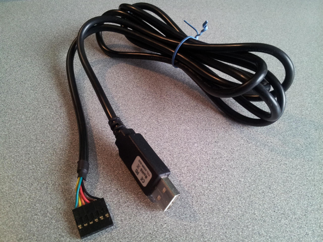
Fig. 789 FTDI cable#
Discussion#
The Beagle side of the FTDI cable has a small triangle on it as shown in FTDI connector which marks the ground pin, pin 1.
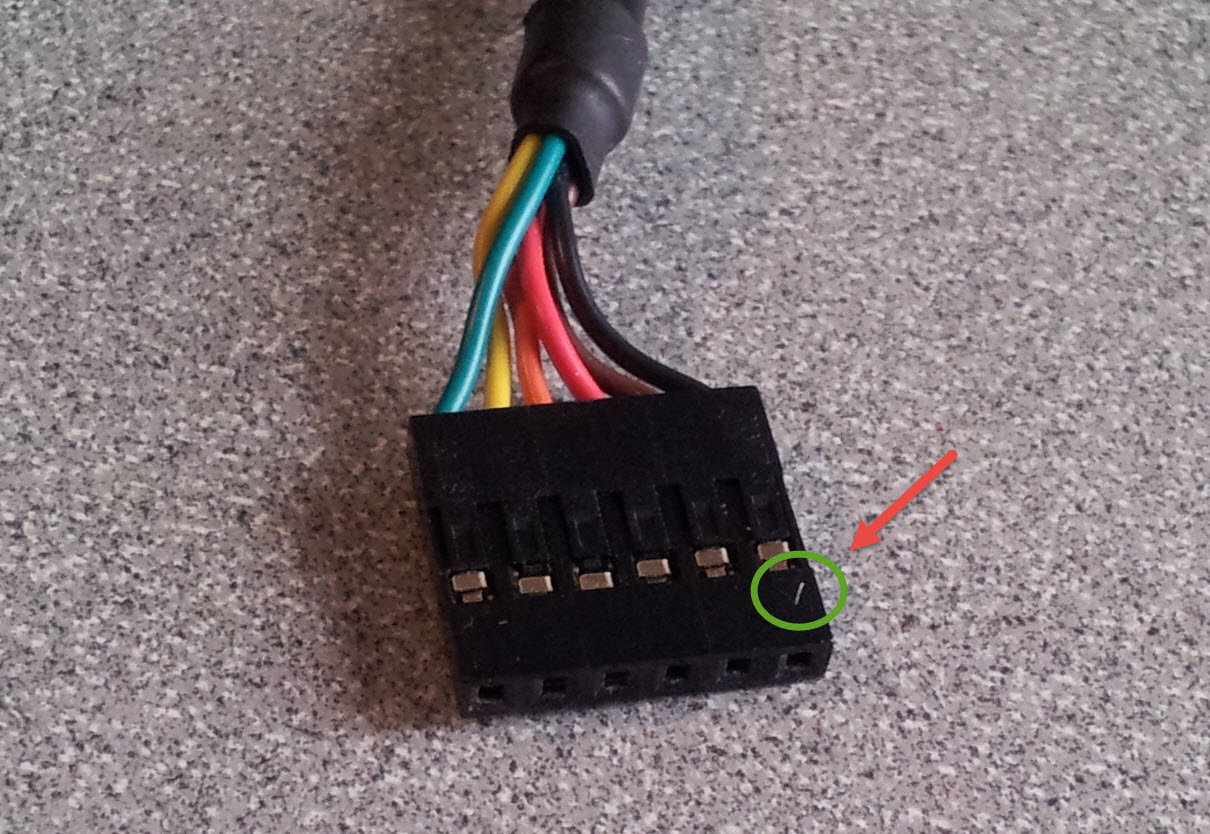
Fig. 790 FTDI connector#
The Wring for FTDI cable to Beagle table shows which pins connect where and FTDI to BB Black is a wiring diagram for the BeagleBone Black.
FTDI pin |
Color |
Black pin |
AI 1 pin |
AI 2 pin |
Function |
|
|---|---|---|---|---|---|---|
0 |
black |
P9_1 |
P8_1 |
P8_1 |
P1_16 |
ground |
4 |
orange |
P9_24 |
P8_43 |
P8_33a |
P1_12 |
rx |
5 |
yellow |
P9_26 |
P8_44 |
P8_31a |
P1_06 |
tx |
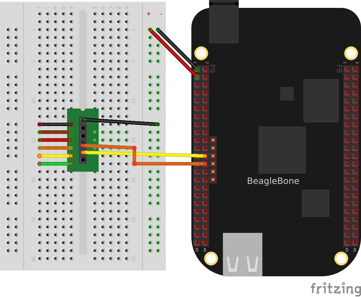
Fig. 791 FTDI to BB Black#
Details#
Two examples of using the UART are presented here. The first (uart1.pru1_0.c) sends a character out the serial port then waits for a character to come in. Once the new character arrives another character is output.
The second example (uart2.pru1_0.c) prints out a string and then waits for characters to arrive. Once an ENTER appears the string is sent back.
Tip
On the Black, either PRU0 and PRU1 can run this code. Both have access to the same UART.
You need to set the pin muxes.
config-pin#
# Configure tx Black
bone$ *config-pin P9_24 pru_uart*
# Configure rx Black
bone$ *config-pin P9_26 pru_uart*

# Configure tx Pocket
bone$ *config-pin P1_06 pru_uart*
# Configure rx Pocket
bone$ *config-pin P1_12 pru_uart*
Note
See Configuring pins on the AI via device trees for configuring pins on the AI. Make sure your rx pins are configured as input pins in the device tree.
For example
DRA7XX_CORE_IOPAD(0x3610, *PIN_INPUT* | MUX_MODE10) // C6: P8.33a:
 1// From: http://git.ti.com/pru-software-support-package/pru-software-support-package/trees/master/examples/am335x/PRU_Hardware_UART
 2// This example was converted to the am5729 by changing the names in pru_uart.h
 3// for the am335x to the more descriptive names for the am5729.
 4// For example  DLL convertes to DIVISOR_REGISTER_LSB_
 5#include <stdint.h>
 6#include <pru_uart.h>
 7#include "resource_table_empty.h"
 8
 9/* The FIFO size on the PRU UART is 16 bytes; however, we are (arbitrarily)
10 * only going to send 8 at a time */
11#define FIFO_SIZE	16
12#define MAX_CHARS	8
13
14void main(void)
15{
16	uint8_t tx;
17	uint8_t rx;
18	uint8_t cnt;
19
20	/*  hostBuffer points to the string to be printed */
21	char* hostBuffer;
22
23	/*** INITIALIZATION ***/
24
25	/* Set up UART to function at 115200 baud - DLL divisor is 104 at 16x oversample
26	 * 192MHz / 104 / 16 = ~115200 */
27	CT_UART.DIVISOR_REGISTER_LSB_ = 104;
28	CT_UART.DIVISOR_REGISTER_MSB_ = 0;
29	CT_UART.MODE_DEFINITION_REGISTER = 0x0;
30
31	/* Enable Interrupts in UART module. This allows the main thread to poll for
32	 * Receive Data Available and Transmit Holding Register Empty */
33	CT_UART.INTERRUPT_ENABLE_REGISTER = 0x7;
34
35	/* If FIFOs are to be used, select desired trigger level and enable
36	 * FIFOs by writing to FCR. FIFOEN bit in FCR must be set first before
37	 * other bits are configured */
38	/* Enable FIFOs for now at 1-byte, and flush them */
39	CT_UART.INTERRUPT_IDENTIFICATION_REGISTER_FIFO_CONTROL_REGISTER = (0x8) | (0x4) | (0x2) | (0x1);
40	//CT_UART.FCR = (0x80) | (0x4) | (0x2) | (0x01); // 8-byte RX FIFO trigger
41
42	/* Choose desired protocol settings by writing to LCR */
43	/* 8-bit word, 1 stop bit, no parity, no break control and no divisor latch */
44	CT_UART.LINE_CONTROL_REGISTER = 3;
45
46	/* Enable loopback for test */
47	CT_UART.MODEM_CONTROL_REGISTER = 0x00;
48
49	/* Choose desired response to emulation suspend events by configuring
50	 * FREE bit and enable UART by setting UTRST and URRST in PWREMU_MGMT */
51	/* Allow UART to run free, enable UART TX/RX */
52	CT_UART.POWERMANAGEMENT_AND_EMULATION_REGISTER = 0x6001;
53
54	/*** END INITIALIZATION ***/
55
56	/* Priming the 'hostbuffer' with a message */
57	hostBuffer = "Hello!  This is a long string\r\n";
58
59	/*** SEND SOME DATA ***/
60
61	/* Let's send/receive some dummy data */
62	while(1) {
63		cnt = 0;
64		while(1) {
65			/* Load character, ensure it is not string termination */
66			if ((tx = hostBuffer[cnt]) == '\0')
67				break;
68			cnt++;
69			CT_UART.RBR_THR_REGISTERS = tx;
70
71			/* Because we are doing loopback, wait until LSR.DR == 1
72			 * indicating there is data in the RX FIFO */
73			while ((CT_UART.LINE_STATUS_REGISTER & 0x1) == 0x0);
74
75			/* Read the value from RBR */
76			rx = CT_UART.RBR_THR_REGISTERS;
77
78			/* Wait for TX FIFO to be empty */
79			while (!((CT_UART.INTERRUPT_IDENTIFICATION_REGISTER_FIFO_CONTROL_REGISTER & 0x2) == 0x2));
80		}
81	}
82
83	/*** DONE SENDING DATA ***/
84
85	/* Disable UART before halting */
86	CT_UART.POWERMANAGEMENT_AND_EMULATION_REGISTER = 0x0;
87
88	/* Halt PRU core */
89	__halt();
90}
Set the following variables so make will know what to compile.
bone$ *make TARGET=uart1.pru0*
/opt/source/pru-cookbook-code/common/Makefile:29: MODEL=TI_AM335x_BeagleBone_Black,TARGET=uart1.pru0
-    Stopping PRU 0
-     copying firmware file /tmp/vsx-examples/uart1.pru0.out to /lib/firmware/am335x-pru0-fw
write_init_pins.sh
-    Starting PRU 0
MODEL   = TI_AM335x_BeagleBone_Black
PROC    = pru
PRUN    = 0
PRU_DIR = /dev/remoteproc/pruss-core0
Now make will compile, load PRU0 and start it.
In a terminal window on your host computer run
host$ *screen /dev/ttyUSB0 115200*
It will initially display the first charters (H) and then as you enter
characters on the keyboard, the rest of the message will appear.
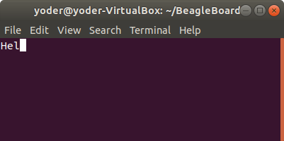
Fig. 792 uart1.pru0.c output#
Here’s the code (uart1.pru1_0.c) that does it.
 1// From: http://git.ti.com/pru-software-support-package/pru-software-support-package/trees/master/examples/am335x/PRU_Hardware_UART
 2// This example was converted to the am5729 by changing the names in pru_uart.h
 3// for the am335x to the more descriptive names for the am5729.
 4// For example  DLL convertes to DIVISOR_REGISTER_LSB_
 5#include <stdint.h>
 6#include <pru_uart.h>
 7#include "resource_table_empty.h"
 8
 9/* The FIFO size on the PRU UART is 16 bytes; however, we are (arbitrarily)
10 * only going to send 8 at a time */
11#define FIFO_SIZE	16
12#define MAX_CHARS	8
13
14void main(void)
15{
16	uint8_t tx;
17	uint8_t rx;
18	uint8_t cnt;
19
20	/*  hostBuffer points to the string to be printed */
21	char* hostBuffer;
22
23	/*** INITIALIZATION ***/
24
25	/* Set up UART to function at 115200 baud - DLL divisor is 104 at 16x oversample
26	 * 192MHz / 104 / 16 = ~115200 */
27	CT_UART.DIVISOR_REGISTER_LSB_ = 104;
28	CT_UART.DIVISOR_REGISTER_MSB_ = 0;
29	CT_UART.MODE_DEFINITION_REGISTER = 0x0;
30
31	/* Enable Interrupts in UART module. This allows the main thread to poll for
32	 * Receive Data Available and Transmit Holding Register Empty */
33	CT_UART.INTERRUPT_ENABLE_REGISTER = 0x7;
34
35	/* If FIFOs are to be used, select desired trigger level and enable
36	 * FIFOs by writing to FCR. FIFOEN bit in FCR must be set first before
37	 * other bits are configured */
38	/* Enable FIFOs for now at 1-byte, and flush them */
39	CT_UART.INTERRUPT_IDENTIFICATION_REGISTER_FIFO_CONTROL_REGISTER = (0x8) | (0x4) | (0x2) | (0x1);
40	//CT_UART.FCR = (0x80) | (0x4) | (0x2) | (0x01); // 8-byte RX FIFO trigger
41
42	/* Choose desired protocol settings by writing to LCR */
43	/* 8-bit word, 1 stop bit, no parity, no break control and no divisor latch */
44	CT_UART.LINE_CONTROL_REGISTER = 3;
45
46	/* Enable loopback for test */
47	CT_UART.MODEM_CONTROL_REGISTER = 0x00;
48
49	/* Choose desired response to emulation suspend events by configuring
50	 * FREE bit and enable UART by setting UTRST and URRST in PWREMU_MGMT */
51	/* Allow UART to run free, enable UART TX/RX */
52	CT_UART.POWERMANAGEMENT_AND_EMULATION_REGISTER = 0x6001;
53
54	/*** END INITIALIZATION ***/
55
56	/* Priming the 'hostbuffer' with a message */
57	hostBuffer = "Hello!  This is a long string\r\n";
58
59	/*** SEND SOME DATA ***/
60
61	/* Let's send/receive some dummy data */
62	while(1) {
63		cnt = 0;
64		while(1) {
65			/* Load character, ensure it is not string termination */
66			if ((tx = hostBuffer[cnt]) == '\0')
67				break;
68			cnt++;
69			CT_UART.RBR_THR_REGISTERS = tx;
70
71			/* Because we are doing loopback, wait until LSR.DR == 1
72			 * indicating there is data in the RX FIFO */
73			while ((CT_UART.LINE_STATUS_REGISTER & 0x1) == 0x0);
74
75			/* Read the value from RBR */
76			rx = CT_UART.RBR_THR_REGISTERS;
77
78			/* Wait for TX FIFO to be empty */
79			while (!((CT_UART.INTERRUPT_IDENTIFICATION_REGISTER_FIFO_CONTROL_REGISTER & 0x2) == 0x2));
80		}
81	}
82
83	/*** DONE SENDING DATA ***/
84
85	/* Disable UART before halting */
86	CT_UART.POWERMANAGEMENT_AND_EMULATION_REGISTER = 0x0;
87
88	/* Halt PRU core */
89	__halt();
90}
Note
I’m using the AI version of the code since it uses variables with more desciptive names.
The first part of the code initializes the UART. Then the line
CT_UART.RBR_THR_REGISTERS = tx; takes a character in tx
and sends it to the transmit buffer on the UART. Think of
this as the UART version of the printf().
Later the line while (!((CT_UART.INTERRUPT_IDENTIFICATION_REGISTER_FIFO_CONTROL_REGISTER & 0x2) == 0x2));
waits for the transmitter FIFO to be empty. This makes sure later characters
won’t overwrite the buffer before they can be sent. The downside is, this will
cause your code to wait on the buffer and it might miss an important
real-time event.
The line while ((CT_UART.LINE_STATUS_REGISTER & 0x1) == 0x0); waits for an input from the
UART (possibly missing something) and rx = CT_UART.RBR_THR_REGISTERS; reads from the
receive register on the UART.
These simple lines should be enough to place in your code to print out debugging information.
  1// From: http://git.ti.com/pru-software-support-package/pru-software-support-package/trees/master/pru_cape/pru_fw/PRU_Hardware_UART
  2
  3#include <stdint.h>
  4#include <pru_uart.h>
  5#include "resource_table_empty.h"
  6
  7/* The FIFO size on the PRU UART is 16 bytes; however, we are (arbitrarily)
  8 * only going to send 8 at a time */
  9#define FIFO_SIZE	16
 10#define MAX_CHARS	8
 11#define BUFFER		40
 12
 13//******************************************************************************
 14//    Print Message Out
 15//      This function take in a string literal of any size and then fill the
 16//      TX FIFO when it's empty and waits until there is info in the RX FIFO
 17//      before returning.
 18//******************************************************************************
 19void PrintMessageOut(volatile char* Message)
 20{
 21	uint8_t cnt, index = 0;
 22
 23	while (1) {
 24		cnt = 0;
 25
 26		/* Wait until the TX FIFO and the TX SR are completely empty */
 27		while (!CT_UART.LSR_bit.TEMT);
 28
 29		while (Message[index] != NULL && cnt < MAX_CHARS) {
 30			CT_UART.THR = Message[index];
 31			index++;
 32			cnt++;
 33		}
 34		if (Message[index] == NULL)
 35			break;
 36	}
 37
 38	/* Wait until the TX FIFO and the TX SR are completely empty */
 39	while (!CT_UART.LSR_bit.TEMT);
 40
 41}
 42
 43//******************************************************************************
 44//    IEP Timer Config
 45//      This function waits until there is info in the RX FIFO and then returns
 46//      the first character entered.
 47//******************************************************************************
 48char ReadMessageIn(void)
 49{
 50	while (!CT_UART.LSR_bit.DR);
 51
 52	return CT_UART.RBR_bit.DATA;
 53}
 54
 55void main(void)
 56{
 57	uint32_t i;
 58	volatile uint32_t not_done = 1;
 59
 60	char rxBuffer[BUFFER];
 61	rxBuffer[BUFFER-1] = NULL; // null terminate the string
 62
 63	/*** INITIALIZATION ***/
 64
 65	/* Set up UART to function at 115200 baud - DLL divisor is 104 at 16x oversample
 66	 * 192MHz / 104 / 16 = ~115200 */
 67	CT_UART.DLL = 104;
 68	CT_UART.DLH = 0;
 69	CT_UART.MDR_bit.OSM_SEL = 0x0;
 70
 71	/* Enable Interrupts in UART module. This allows the main thread to poll for
 72	 * Receive Data Available and Transmit Holding Register Empty */
 73	CT_UART.IER = 0x7;
 74
 75	/* If FIFOs are to be used, select desired trigger level and enable
 76	 * FIFOs by writing to FCR. FIFOEN bit in FCR must be set first before
 77	 * other bits are configured */
 78	/* Enable FIFOs for now at 1-byte, and flush them */
 79	CT_UART.FCR = (0x80) | (0x8) | (0x4) | (0x2) | (0x01); // 8-byte RX FIFO trigger
 80
 81	/* Choose desired protocol settings by writing to LCR */
 82	/* 8-bit word, 1 stop bit, no parity, no break control and no divisor latch */
 83	CT_UART.LCR = 3;
 84
 85	/* If flow control is desired write appropriate values to MCR. */
 86	/* No flow control for now, but enable loopback for test */
 87	CT_UART.MCR = 0x00;
 88
 89	/* Choose desired response to emulation suspend events by configuring
 90	 * FREE bit and enable UART by setting UTRST and URRST in PWREMU_MGMT */
 91	/* Allow UART to run free, enable UART TX/RX */
 92	CT_UART.PWREMU_MGMT_bit.FREE = 0x1;
 93	CT_UART.PWREMU_MGMT_bit.URRST = 0x1;
 94	CT_UART.PWREMU_MGMT_bit.UTRST = 0x1;
 95
 96	/* Turn off RTS and CTS functionality */
 97	CT_UART.MCR_bit.AFE = 0x0;
 98	CT_UART.MCR_bit.RTS = 0x0;
 99
100	/*** END INITIALIZATION ***/
101
102	while(1) {
103		/* Print out greeting message */
104		PrintMessageOut("Hello you are in the PRU UART demo test please enter some characters\r\n");
105
106		/* Read in characters from user, then echo them back out */
107		for (i = 0; i < BUFFER-1 ; i++) {
108			rxBuffer[i] = ReadMessageIn();
109			if(rxBuffer[i] == '\r') {	// Quit early if ENTER is hit.
110				rxBuffer[i+1] = NULL;
111				break;
112			}
113		}
114
115		PrintMessageOut("you typed:\r\n");
116		PrintMessageOut(rxBuffer);
117		PrintMessageOut("\r\n");
118	}
119
120	/*** DONE SENDING DATA ***/
121	/* Disable UART before halting */
122	CT_UART.PWREMU_MGMT = 0x0;
123
124	/* Halt PRU core */
125	__halt();
126}
If you want to try uart2.pru0.c, run the following:
bone$ *make TARGET=uart2.pru0*
/opt/source/pru-cookbook-code/common/Makefile:29: MODEL=TI_AM335x_BeagleBone_Black,TARGET=uart2.pru0
-    Stopping PRU 0
-     copying firmware file /tmp/vsx-examples/uart2.pru0.out to /lib/firmware/am335x-pru0-fw
write_init_pins.sh
-    Starting PRU 0
MODEL   = TI_AM335x_BeagleBone_Black
PROC    = pru
PRUN    = 0
PRU_DIR = /dev/remoteproc/pruss-core0
You will see:
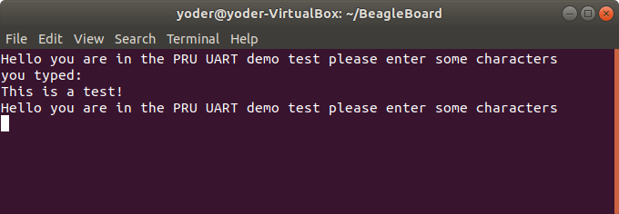
Fig. 793 uart2.pru0.c output#
Type a few characters and hit ENTER. The PRU will playback what you typed, but it won’t echo it as you type.
uart2.pru0.c defines PrintMessageOut() which is passed a string that is
sent to the UART. It takes advantage of the eight character FIFO on the UART.
Be careful using it because it also uses while (!CT_UART.LSR_bit.TEMT); to
wait for the FIFO to empty, which may cause your code to miss something.
uart2.pru1_0.c is the code that does it.
  1// From: http://git.ti.com/pru-software-support-package/pru-software-support-package/trees/master/pru_cape/pru_fw/PRU_Hardware_UART
  2
  3#include <stdint.h>
  4#include <pru_uart.h>
  5#include "resource_table_empty.h"
  6
  7/* The FIFO size on the PRU UART is 16 bytes; however, we are (arbitrarily)
  8 * only going to send 8 at a time */
  9#define FIFO_SIZE	16
 10#define MAX_CHARS	8
 11#define BUFFER		40
 12
 13//******************************************************************************
 14//    Print Message Out
 15//      This function take in a string literal of any size and then fill the
 16//      TX FIFO when it's empty and waits until there is info in the RX FIFO
 17//      before returning.
 18//******************************************************************************
 19void PrintMessageOut(volatile char* Message)
 20{
 21	uint8_t cnt, index = 0;
 22
 23	while (1) {
 24		cnt = 0;
 25
 26		/* Wait until the TX FIFO and the TX SR are completely empty */
 27		while (!CT_UART.LINE_STATUS_REGISTER_bit.TEMT);
 28
 29		while (Message[index] != NULL && cnt < MAX_CHARS) {
 30			CT_UART.RBR_THR_REGISTERS = Message[index];
 31			index++;
 32			cnt++;
 33		}
 34		if (Message[index] == NULL)
 35			break;
 36	}
 37
 38	/* Wait until the TX FIFO and the TX SR are completely empty */
 39	while (!CT_UART.LINE_STATUS_REGISTER_bit.TEMT);
 40
 41}
 42
 43//******************************************************************************
 44//    IEP Timer Config
 45//      This function waits until there is info in the RX FIFO and then returns
 46//      the first character entered.
 47//******************************************************************************
 48char ReadMessageIn(void)
 49{
 50	while (!CT_UART.LINE_STATUS_REGISTER_bit.DR);
 51
 52	return CT_UART.RBR_THR_REGISTERS_bit.DATA;
 53}
 54
 55void main(void)
 56{
 57	uint32_t i;
 58	volatile uint32_t not_done = 1;
 59
 60	char rxBuffer[BUFFER];
 61	rxBuffer[BUFFER-1] = NULL; // null terminate the string
 62
 63	/*** INITIALIZATION ***/
 64
 65	/* Set up UART to function at 115200 baud - DLL divisor is 104 at 16x oversample
 66	 * 192MHz / 104 / 16 = ~115200 */
 67	CT_UART.DIVISOR_REGISTER_LSB_ = 104;
 68	CT_UART.DIVISOR_REGISTER_MSB_ = 0;
 69	CT_UART.MODE_DEFINITION_REGISTER_bit.OSM_SEL = 0x0;
 70
 71	/* Enable Interrupts in UART module. This allows the main thread to poll for
 72	 * Receive Data Available and Transmit Holding Register Empty */
 73	CT_UART.INTERRUPT_ENABLE_REGISTER = 0x7;
 74
 75	/* If FIFOs are to be used, select desired trigger level and enable
 76	 * FIFOs by writing to FCR. FIFOEN bit in FCR must be set first before
 77	 * other bits are configured */
 78	/* Enable FIFOs for now at 1-byte, and flush them */
 79	CT_UART.INTERRUPT_IDENTIFICATION_REGISTER_FIFO_CONTROL_REGISTER = (0x80) | (0x8) | (0x4) | (0x2) | (0x01); // 8-byte RX FIFO trigger
 80
 81	/* Choose desired protocol settings by writing to LCR */
 82	/* 8-bit word, 1 stop bit, no parity, no break control and no divisor latch */
 83	CT_UART.LINE_CONTROL_REGISTER = 3;
 84
 85	/* If flow control is desired write appropriate values to MCR. */
 86	/* No flow control for now, but enable loopback for test */
 87	CT_UART.MODEM_CONTROL_REGISTER = 0x00;
 88
 89	/* Choose desired response to emulation suspend events by configuring
 90	 * FREE bit and enable UART by setting UTRST and URRST in PWREMU_MGMT */
 91	/* Allow UART to run free, enable UART TX/RX */
 92	CT_UART.POWERMANAGEMENT_AND_EMULATION_REGISTER_bit.FREE = 0x1;
 93	CT_UART.POWERMANAGEMENT_AND_EMULATION_REGISTER_bit.URRST = 0x1;
 94	CT_UART.POWERMANAGEMENT_AND_EMULATION_REGISTER_bit.UTRST = 0x1;
 95
 96	/* Turn off RTS and CTS functionality */
 97	CT_UART.MODEM_CONTROL_REGISTER_bit.AFE = 0x0;
 98	CT_UART.MODEM_CONTROL_REGISTER_bit.RTS = 0x0;
 99
100	/*** END INITIALIZATION ***/
101
102	while(1) {
103		/* Print out greeting message */
104		PrintMessageOut("Hello you are in the PRU UART demo test please enter some characters\r\n");
105
106		/* Read in characters from user, then echo them back out */
107		for (i = 0; i < BUFFER-1 ; i++) {
108			rxBuffer[i] = ReadMessageIn();
109			if(rxBuffer[i] == '\r') {	// Quit early if ENTER is hit.
110				rxBuffer[i+1] = NULL;
111				break;
112			}
113		}
114
115		PrintMessageOut("you typed:\r\n");
116		PrintMessageOut(rxBuffer);
117		PrintMessageOut("\r\n");
118	}
119
120	/*** DONE SENDING DATA ***/
121	/* Disable UART before halting */
122	CT_UART.POWERMANAGEMENT_AND_EMULATION_REGISTER = 0x0;
123
124	/* Halt PRU core */
125	__halt();
126}
More complex examples can be built using the principles shown in these examples.
Copyright#
 1/*
 2 * Copyright (C) 2015 Texas Instruments Incorporated - http://www.ti.com/
 3 *
 4 *
 5 * Redistribution and use in source and binary forms, with or without
 6 * modification, are permitted provided that the following conditions
 7 * are met:
 8 *
 9 *	* Redistributions of source code must retain the above copyright
10 *	  notice, this list of conditions and the following disclaimer.
11 *
12 *	* Redistributions in binary form must reproduce the above copyright
13 *	  notice, this list of conditions and the following disclaimer in the
14 *	  documentation and/or other materials provided with the
15 *	  distribution.
16 *
17 *	* Neither the name of Texas Instruments Incorporated nor the names of
18 *	  its contributors may be used to endorse or promote products derived
19 *	  from this software without specific prior written permission.
20 *
21 * THIS SOFTWARE IS PROVIDED BY THE COPYRIGHT HOLDERS AND CONTRIBUTORS
22 * "AS IS" AND ANY EXPRESS OR IMPLIED WARRANTIES, INCLUDING, BUT NOT
23 * LIMITED TO, THE IMPLIED WARRANTIES OF MERCHANTABILITY AND FITNESS FOR
24 * A PARTICULAR PURPOSE ARE DISCLAIMED. IN NO EVENT SHALL THE COPYRIGHT
25 * OWNER OR CONTRIBUTORS BE LIABLE FOR ANY DIRECT, INDIRECT, INCIDENTAL,
26 * SPECIAL, EXEMPLARY, OR CONSEQUENTIAL DAMAGES (INCLUDING, BUT NOT
27 * LIMITED TO, PROCUREMENT OF SUBSTITUTE GOODS OR SERVICES; LOSS OF USE,
28 * DATA, OR PROFITS; OR BUSINESS INTERRUPTION) HOWEVER CAUSED AND ON ANY
29 * THEORY OF LIABILITY, WHETHER IN CONTRACT, STRICT LIABILITY, OR TORT
30 * (INCLUDING NEGLIGENCE OR OTHERWISE) ARISING IN ANY WAY OUT OF THE USE
31 * OF THIS SOFTWARE, EVEN IF ADVISED OF THE POSSIBILITY OF SUCH DAMAGE.
32 */
Footnotes